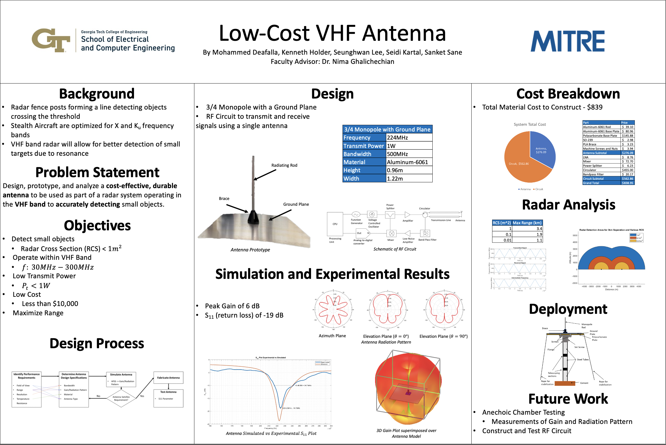
What is a VHF Antenna? It is a device made to transmit and receive radio frequenies at the very high frequency (VHF) radio wave range. The VHF frequency range -- 30 to 300 MHz -- is commonly used to transmit television broadcasts and FM radio. However, in our project, our motivation is to design a self-deploying VHF antenna to integrate into a low cost, low power radar system designed to detect stealthy, low altitude, high speed, targets. We seek to implement a continuous wave radar system that can be deployed as on a series of fence-posts, with little-human installation.
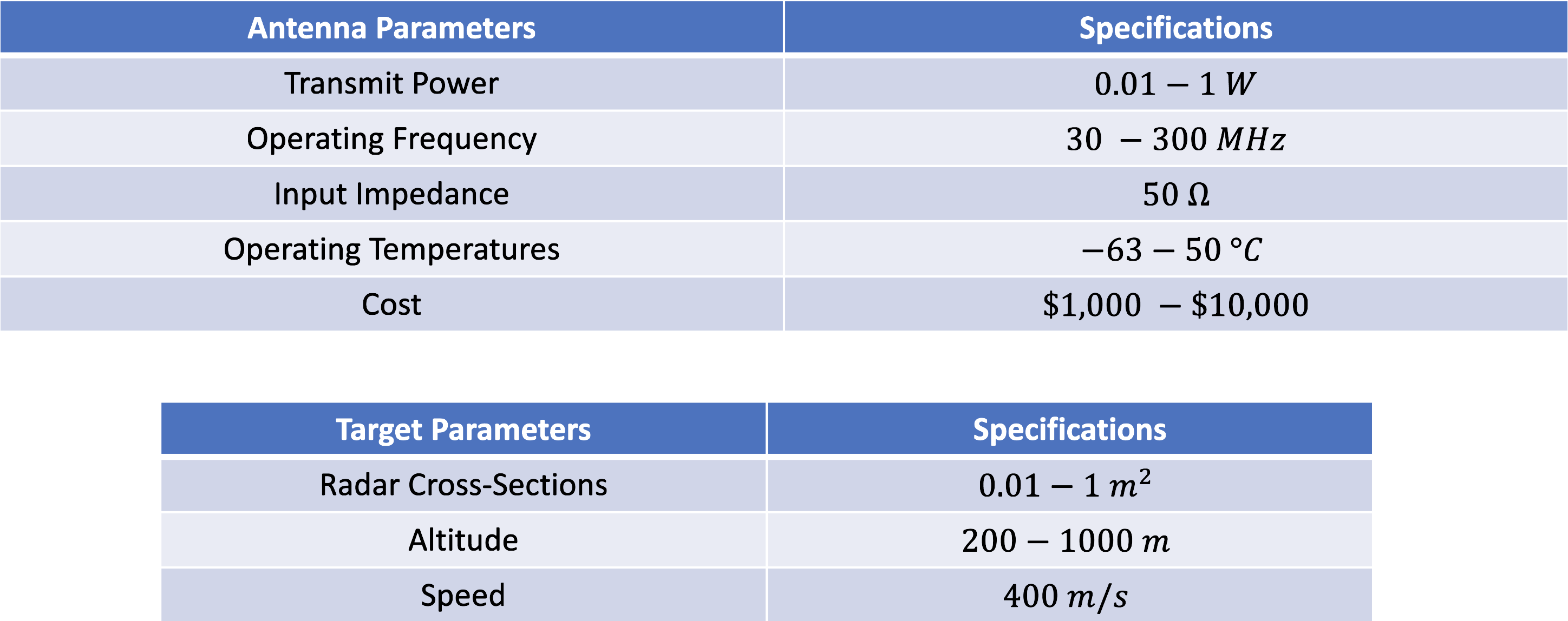
Qualitative Requirements
Quantitative Requirements
Technical Review Papers
Project Proposal
Project Summary
Proposal Presentation
Final Presentation
Final Written Report
Final Video
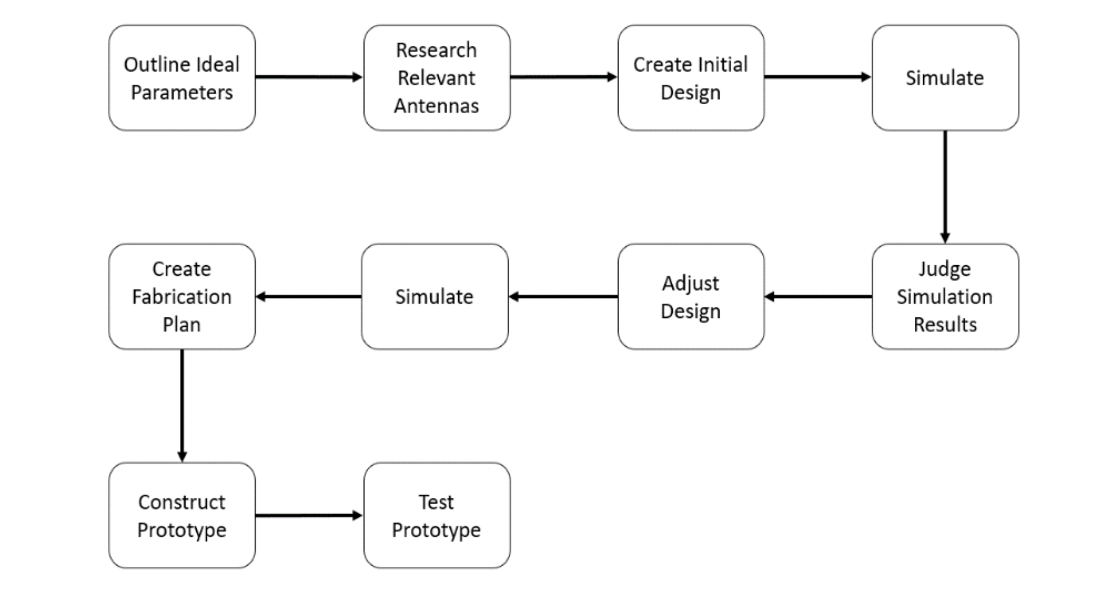
This is our design approach that we came up with to successfully implement our design of the VHF antenna.
The Ideal Antenna
- Modeled an antenna using ideal and desired antenna parameters
- Gain – High enough to allow for low power signals on small RCS
- G0 = 8 dB
- Radiation Pattern – covering the upper hemisphere equally
- D α sin(θ) |0<θ<π
- HPBW – Wide coverage that avoids ground scatter
- 160°
- S11 ⩽ -20 dB
- SLL = −20dB
- Zin = 50Ω
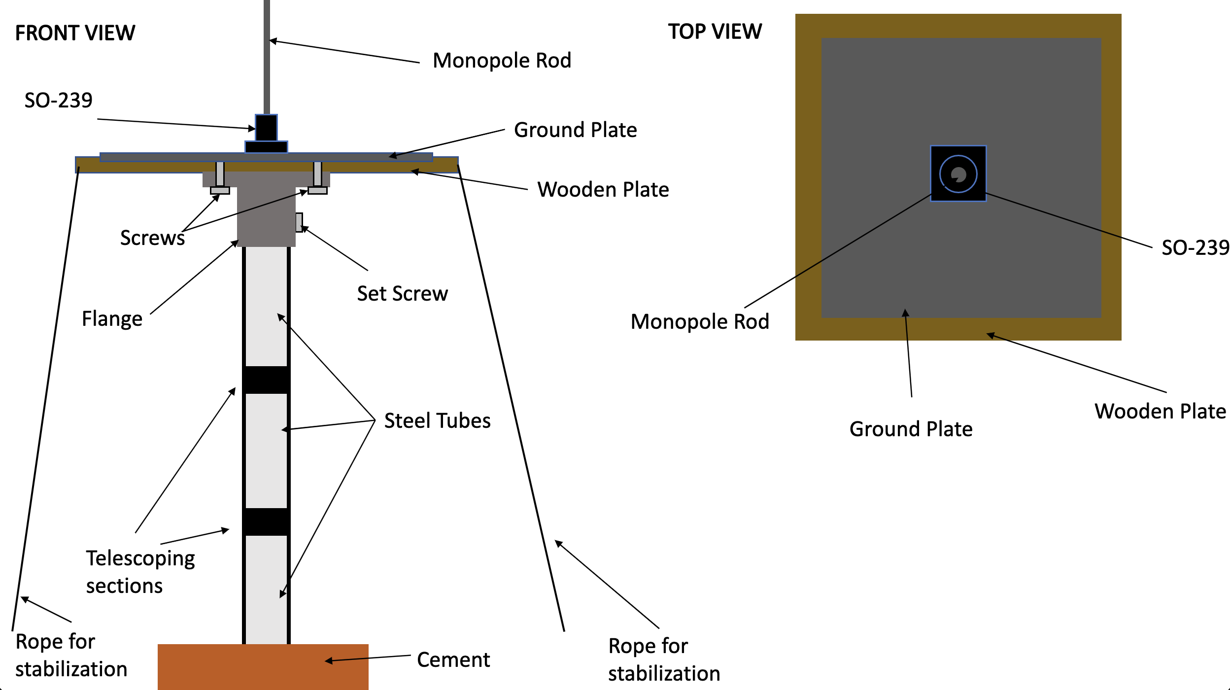
Antenna Design Geometry
We had two choices of antenna design geometry to choose from.
Plan for Design
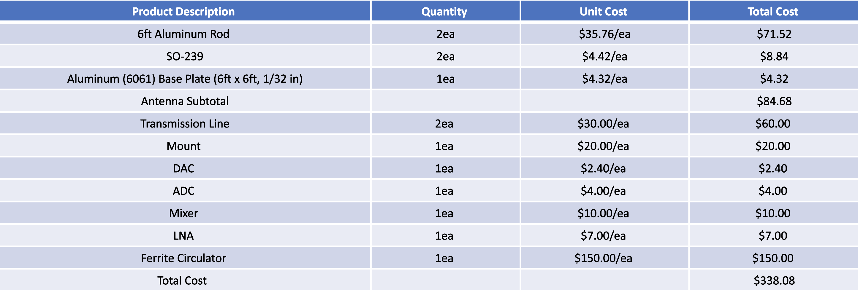
Costs for Fabrication
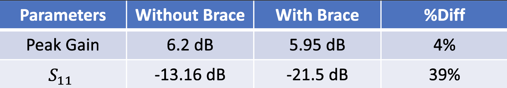
We later realized that we would need some kind of bracing mechanism to support the monopole rod.
Bracing Mechanism
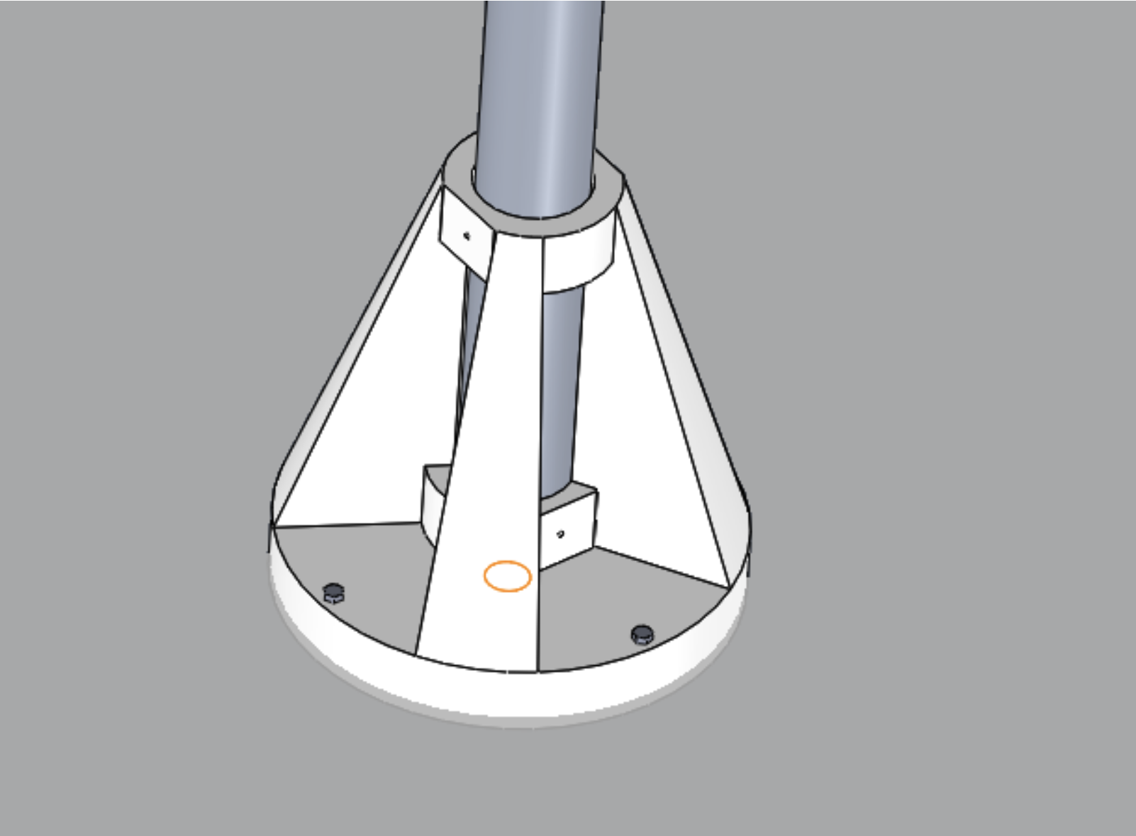
The bracing mechanism was 3D printed using PLA material here in the invention studio, so there are no added costs.
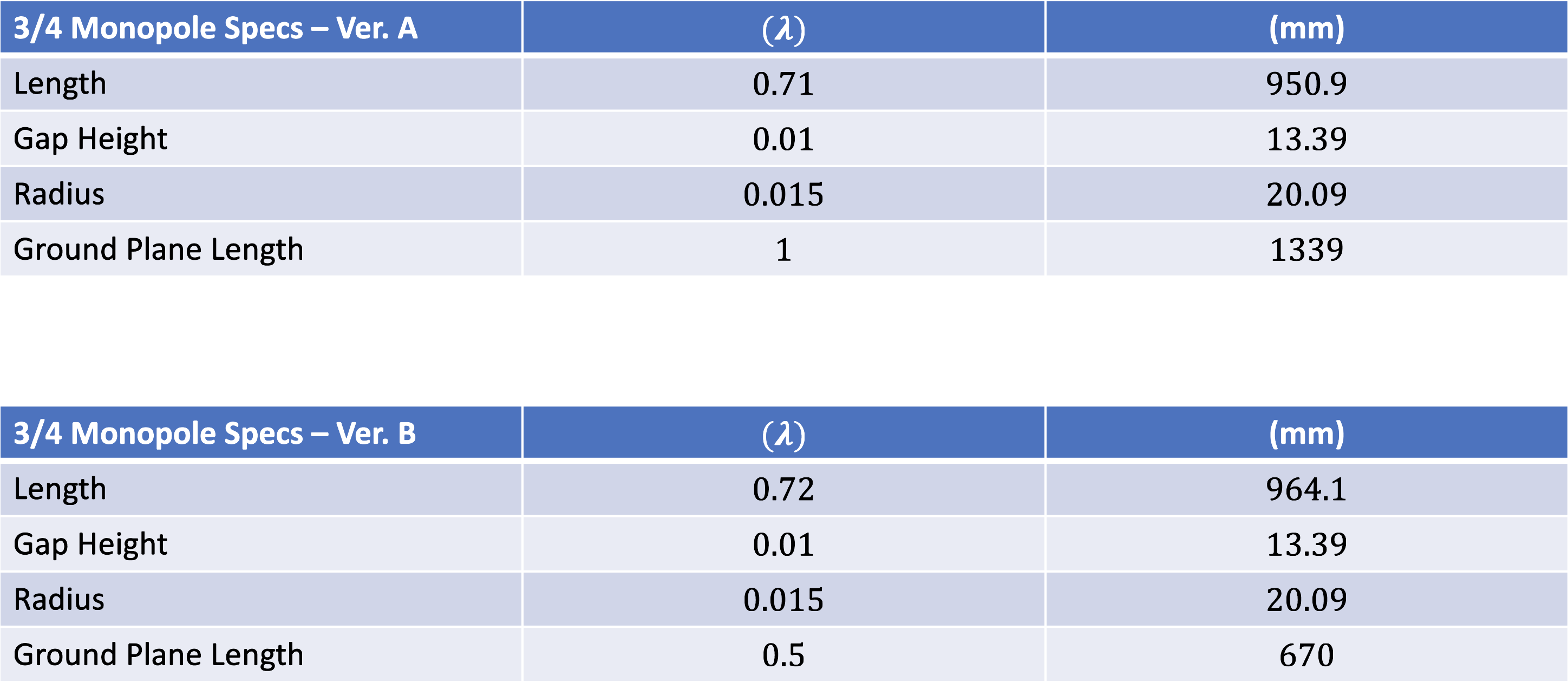
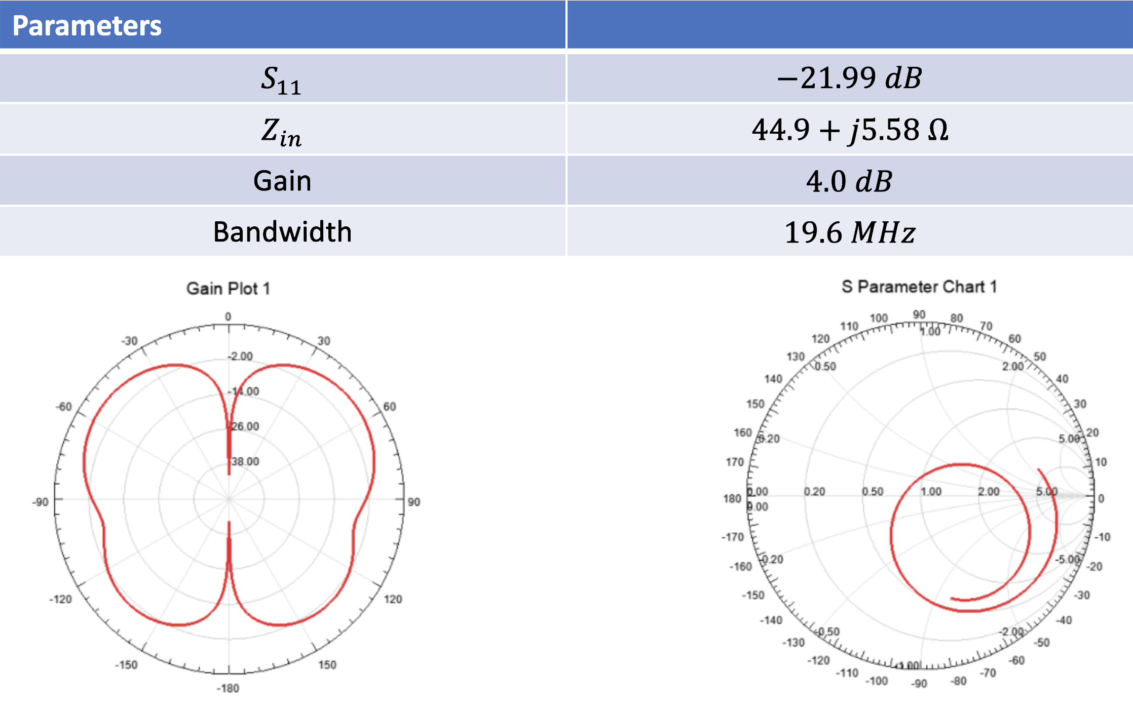
Antenna Simulation Results Ver. A
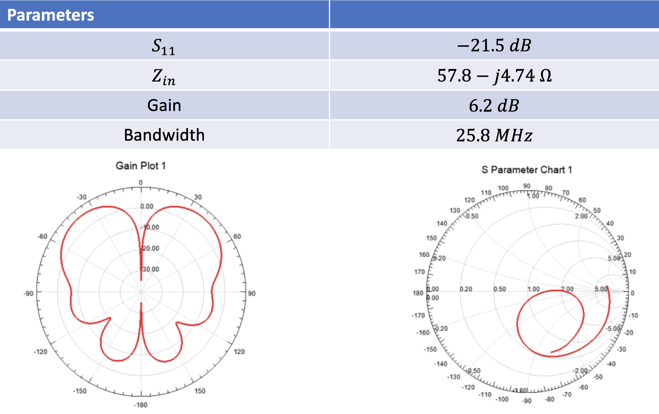
Antenna Simulation Results Ver. B
We ended up choosing to continue with version A.
Simulation Report
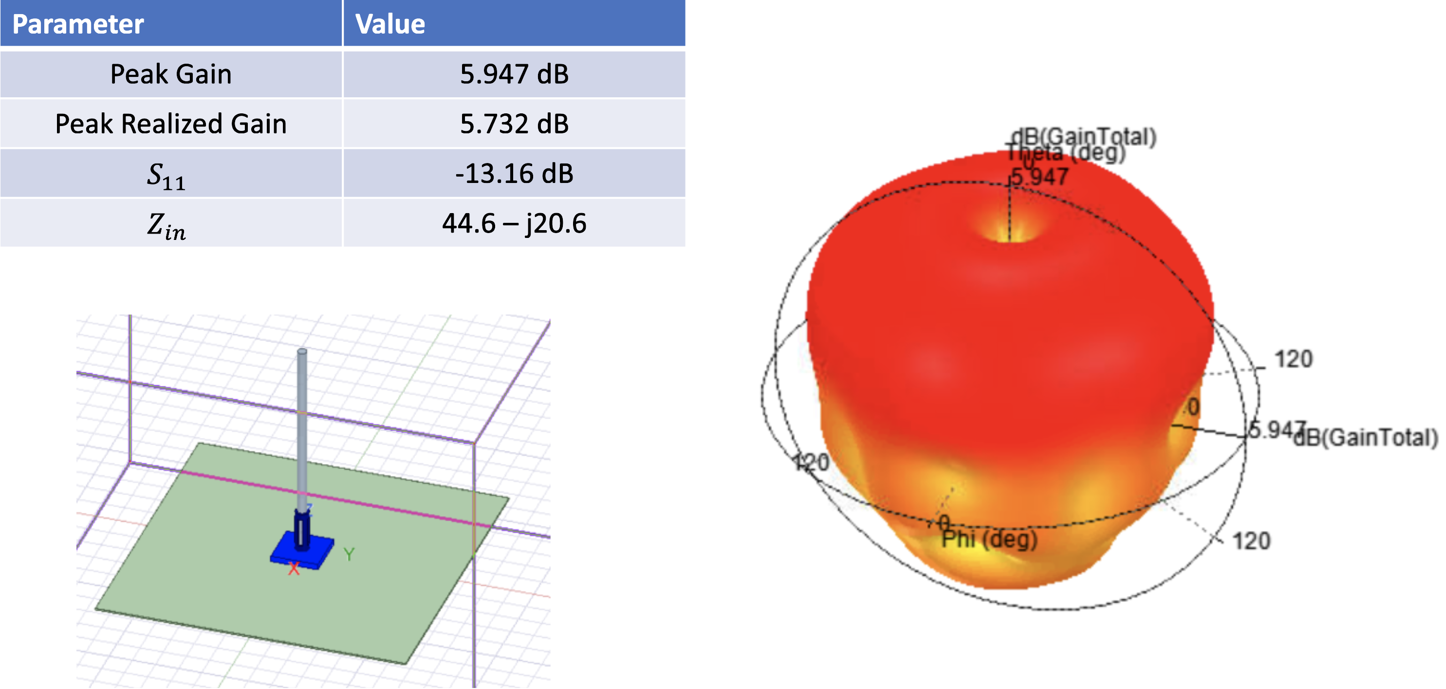
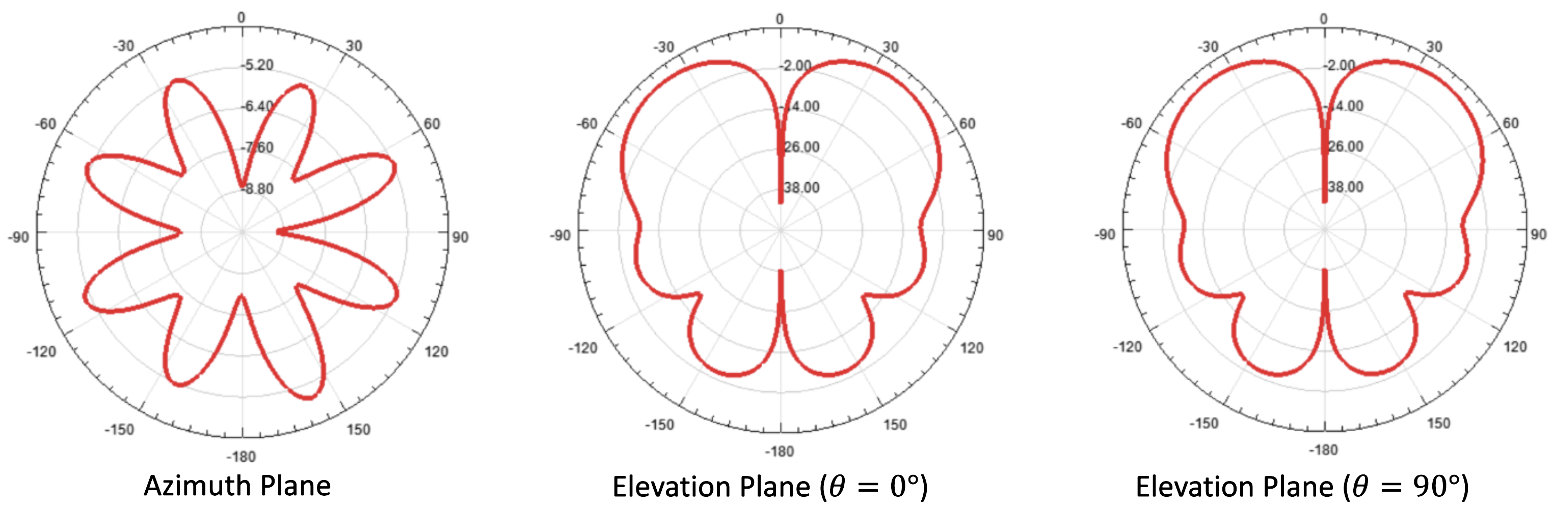
Radiation Patterns
Effect of Brace Mechanism
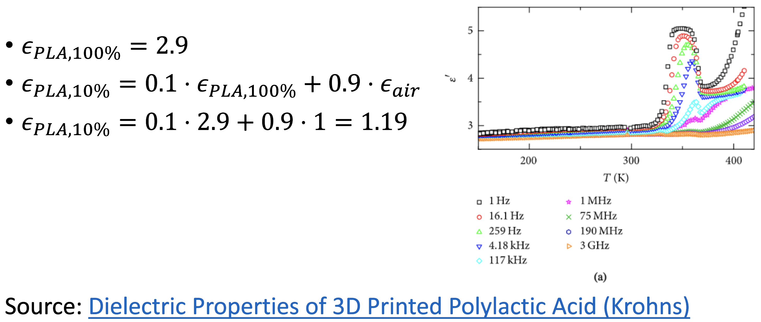
PLA Dielectric Constant
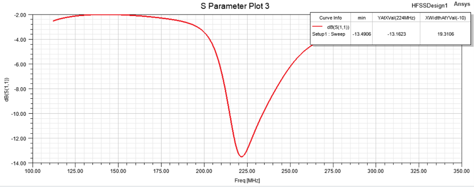
Return Loss with εPLA, 10%
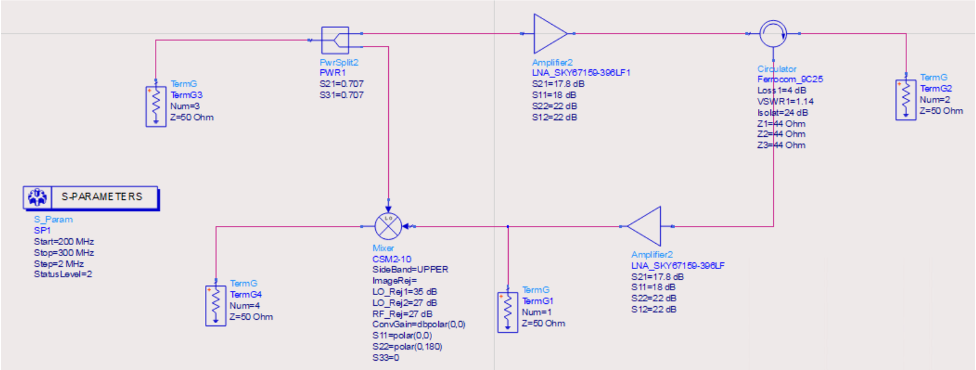
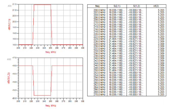
ADS Simulation of Electronic Circuit

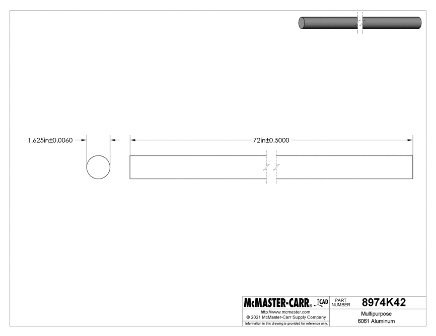
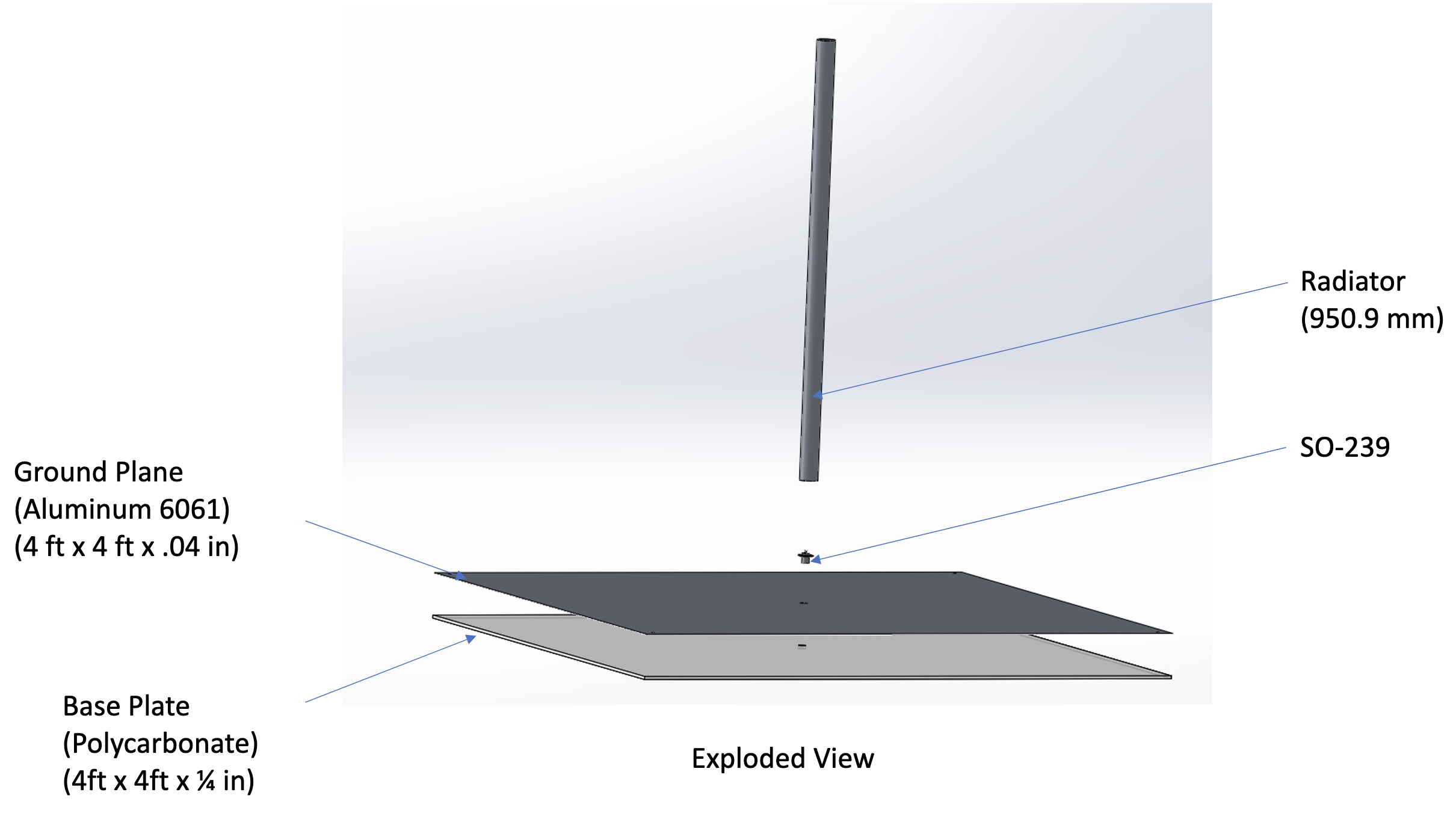
Aluminum Rod -- Antenna
- Aluminum 6061
- Best conductivity in the budget category
- Lightweight, Cheap, and Weather Resistant
- 6ft long
- Need only 950mm
- The rest is experimental stock
- 1-5/8 in diameter
Aluminum Sheet -- Ground Plane
- Aluminum 6061
- 4ft x 4ft area
- 0.04in thick
- Too expensive to get thicker aluminum
- Need just the surface
- Will have supporting material
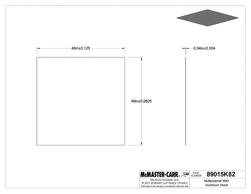
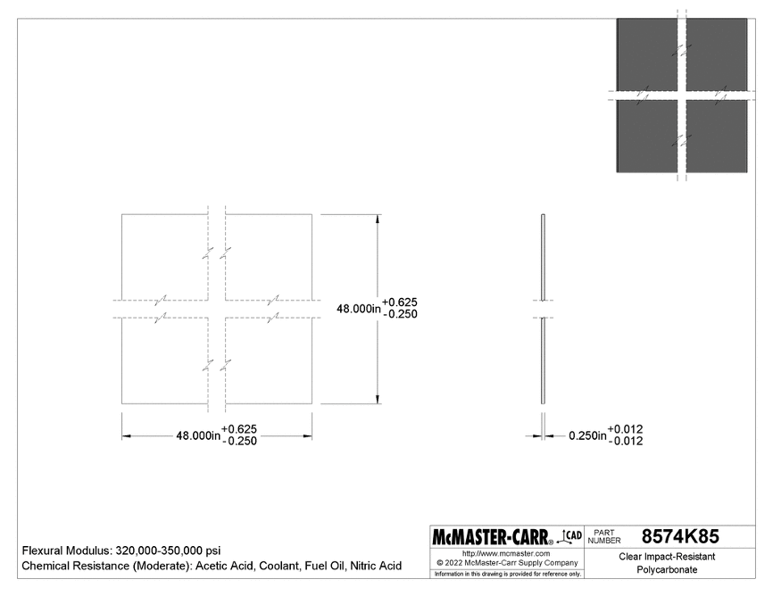
Polycarbonate Sheet – Supporting Material
- Clear Impact-Resistant Polycarbonate
- 4ft x 4ft area
- 1/4in thick
- Acts as the support for the thin Aluminum Ground Plane
3D Printed Brace
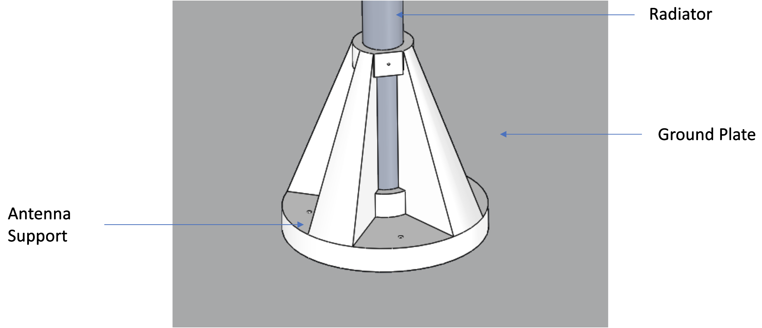
Another Angle of Antenna Construction
Fully Constructed Antenna

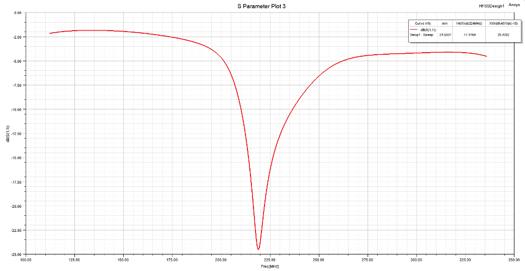
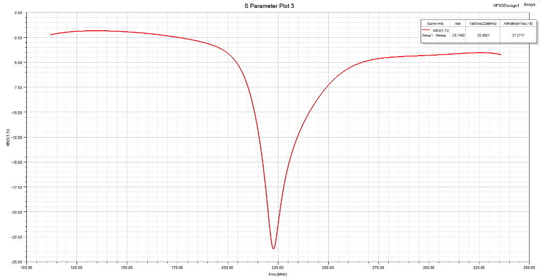
We used a network analyzer to perform an S11 measurement on the constructed antenna.
Comparison of Simulated vs Experimental Results
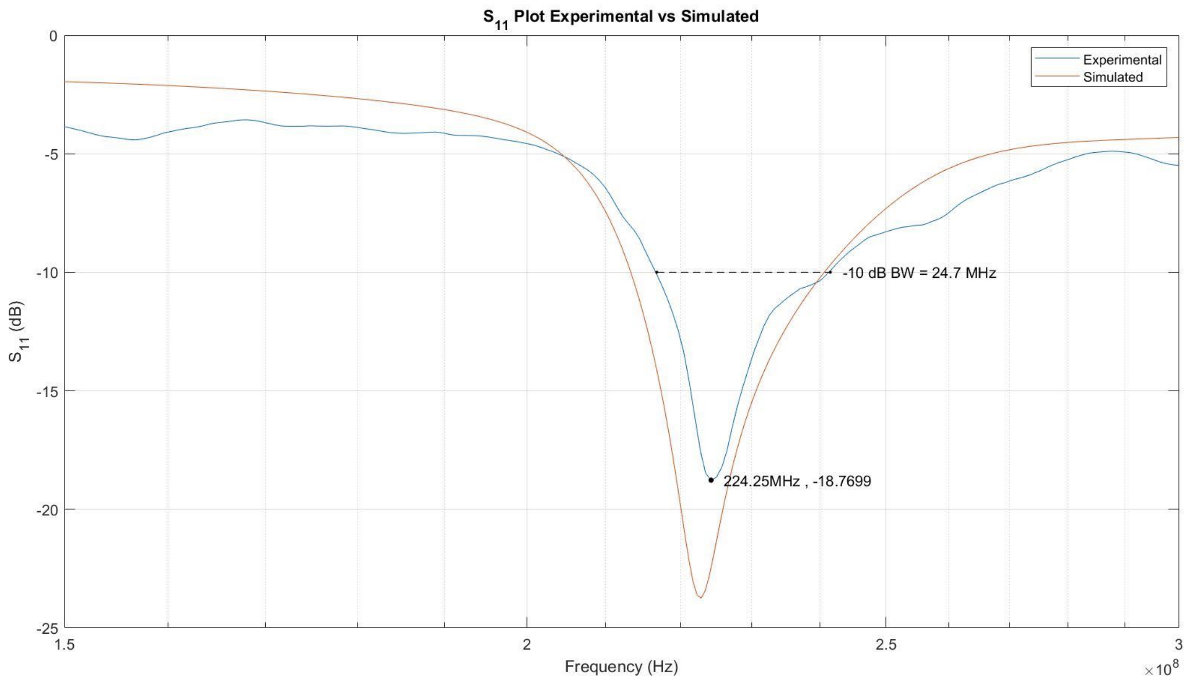
Analysis of Results
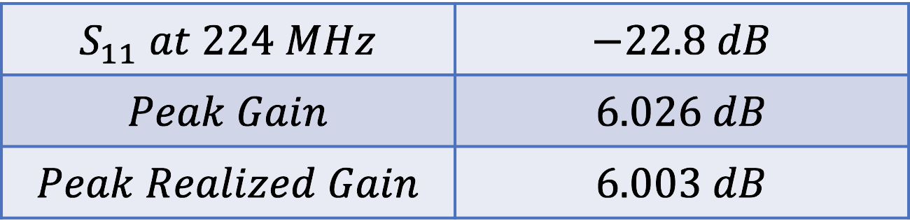
- Resonant Frequency (fr) is at desired frequency of 224 MHz
- However, S11 at fr is significantly lower than expected
- -22 dB vs -19 dB
- We theorize this is due to a poor electric connection between the RF connector and the radiating element
- Initially, we decided against soldering the prototype because it would make its transportation difficult between machining areas and lab
Designed vs. Ideal Comparison

Future Steps
- Improving Electrical Connectivity
- Placing set screws in brace to apply more pressure to rod
- Soldering RF connector pin to rod